
Views: 222 Author: Farwise Lighting Publish Time: 2026-09-30 Origin: Site


Content Menu
● What Is TRIAC Dimming for LEDs?
>> How Does the LED Driver Interpret the Dimmer?
● Leading-Edge vs Trailing-Edge Dimming: Which Works With LEDs?
● Where Does TRIAC Dimming Fit in Furniture Lighting?
>> Under-Cabinet Task Lighting
>> Wardrobe and Closet Lighting
>> Bedroom and Bed-Frame Accent Lighting
● How to Specify a Compatible TRIAC LED System
● A Mockup That Reveals Dimming Problems Early
● Why Do TRIAC-Dimmed LEDs Flicker, Buzz, or Stay On?
● When Should You Choose Another Dimming Method?
● What Should an OEM/ODM Buyer Send the Manufacturer?
● Frequently Asked Questions About TRIAC LED Dimming
>> 1.Can a TRIAC dimmer control LED strip lights directly?
>> 2.Are all dimmable LED power supplies compatible with TRIAC dimmers?
>> 3.Is trailing-edge dimming always better for cabinet lights?
>> 4.Why does a cabinet light remain faintly lit after switching off?
>> 5.Can several furniture lighting zones share one wall dimmer?
>> 6.Does a smart switch eliminate the need for a compatible LED driver?
>> 7.How can a buyer reduce flicker before a large OEM/ODM order?
TRIAC dimming for LED lights can make a kitchen, wardrobe, or bedroom feel more adaptable without adding a separate control network. But a dimmable wall switch alone does not make an LED cabinet light or silicone strip dim smoothly. The dimmer, LED power supply, and light source must work as a system. This guide explains that system, the questions to ask before ordering, and the checks that help prevent flicker after installation.

A traditional TRIAC dimmer controls alternating-current power by delaying conduction at the beginning of each half-cycle. This is called forward-phase or leading-edge dimming. The longer the delay, the less of the waveform reaches the connected load. An incandescent filament responds directly to that change; an LED generally relies on a driver or power supply to interpret it and regulate the light.
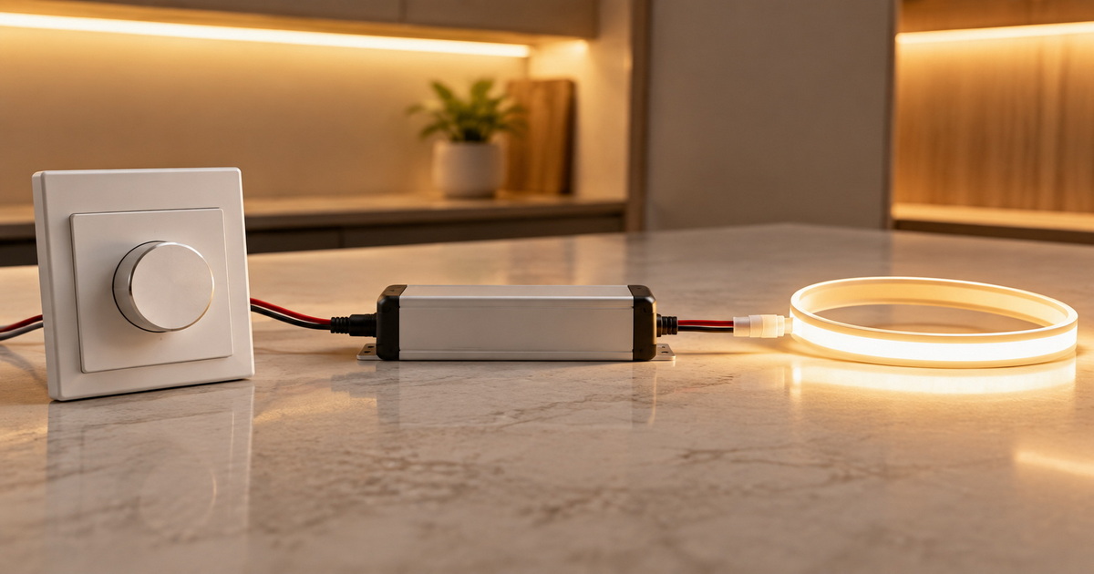
In furniture lighting, the usual arrangement is straightforward: the wall control sends a phase-cut AC signal to a compatible dimmable power supply; that supply then powers the low-voltage cabinet light, wardrobe light, or silicone strip. A standard non-dimmable supply cannot be assumed to interpret a phase-cut signal. Nor should a low-voltage strip be connected directly to a mains dimmer.
People often use "TRIAC dimming" as shorthand for all wall-switch phase-cut dimming. Strictly speaking, a TRIAC is associated with traditional forward-phase control. Many trailing-edge controls use different electronic switching devices. That distinction matters when a supplier says a driver is "TRIAC compatible": ask which phase-cut mode it actually supports.
The wall dimmer changes the shape of the incoming AC waveform. A compatible driver reads that change and adjusts its output to the LEDs. The final result depends on the driver's design, the dimmer, and the connected light—not merely on whether each component carries a "dimmable" label.
The control position also does not necessarily match perceived brightness. A smooth-looking slider may produce an abrupt change near the bottom if the driver has a poor dimming curve. Ask for the usable dimming range and evaluate it with the actual light source, especially where a soft nighttime glow is the objective.
Forward-phase and reverse-phase controls cut different portions of the AC waveform. Neither is universally better for LEDs. The correct choice is the mode documented for the specific LED driver and dimmer combination.
| Control type | How it operates | What to verify for furniture lighting |
|---|---|---|
| Leading-edge / forward-phase | Delays the start of conduction in each AC half-cycle | The driver explicitly supports forward-phase control, and the wall dimmer is rated for LED loads. |
| Trailing-edge / reverse-phase | Ends conduction before each half-cycle finishes | The driver explicitly supports reverse-phase control, and the chosen control works with the available wiring. |
| Phase-adaptive | Offers selectable or automatic phase-control behavior | The installed mode matches the driver's instructions; the complete assembly is tested. |
A trailing-edge dimmer may work particularly well with a compatible electronic driver. Yet some LED drivers are specified for leading-edge only. Do not replace a compatibility check with a blanket rule such as "all LEDs need trailing-edge dimmers." Equally, do not apply an arbitrary fraction of an incandescent dimmer rating to estimate its LED capacity. Use the manufacturer's LED-specific load limits and tested combinations.
The value of phase-cut control is practical: where suitable wall wiring already exists, a compatible switch and power supply can offer familiar, accessible brightness adjustment. It can suit both residential cabinetry and hospitality millwork. The harder part is making every illuminated element behave consistently.
An under-cabinet run should be bright enough for food preparation but comfortable when the kitchen becomes a social space. Specify the power supply and dimmer together. If several cabinet sections share a control, test all sections connected—not just a short sample strip. Look for even starts, consistent brightness, and no delayed switch-on at the low end.
Wardrobe lighting often combines door sensors or motion switches with LED profiles. Before selecting a wall dimmer, establish which device actually switches the load and whether its output can be dimmed. A sensor, controller, and phase-cut driver are not automatically interchangeable. Decide whether users need dimming, automatic on/off control, or both, then validate the intended sequence.
Bathroom cabinets introduce placement and moisture concerns. Confirm the light, connectors, and power supply are suitable for their actual installation locations. Keep service access in mind, and have a qualified installer assess the applicable electrical requirements. A pleasing dimming effect does not compensate for equipment installed in an unsuitable environment.
Concealed silicone strips can create a gentler evening scene around a bed frame or headboard. Here the low end matters more than peak brightness. Ask whether the system starts reliably from its dimmest setting, whether the strip appears uniform through the diffuser, and whether a visible glow remains after the switch is off.
For buyers and designers, the critical unit of purchase is the complete control chain, not an attractive LED strip plus a separately chosen dimmer. The following workflow turns a vague "dimmable" request into an order that can be checked.
1. Map the installation. Identify each lighting zone, the control point, the LED modules, and the planned location of every power supply. Note access for inspection or replacement.
2. Confirm the LED load. Ask whether each cabinet light, wardrobe light, or strip requires a constant-voltage or constant-current supply. Match the supplier's documented electrical requirements without substituting one type for the other.
3. Choose the control method. If the project calls for an existing wall dimmer, request a phase-cut-dimmable supply compatible with its documented mode. For a new build, compare other control approaches before locking in the wiring.
4. Check the dimmer's LED rating. Review both its minimum and maximum LED load guidance, the number of connected supplies, and any manufacturer's compatibility list. Do not infer LED capacity from an incandescent rating.
5. Check the physical installation. Determine whether the selected wall control requires a neutral conductor and whether its location and enclosure suit the project. Leave mains wiring to a qualified electrician.
6. Approve a working sample. Test the actual switch, supply, cable arrangement, and LED load together. Record the accepted components so later substitutions do not silently change the result.
A supplier's compatibility list is a useful starting point, not a substitute for a project mockup. An apparently small change in driver design or dimmer model can change low-end behavior. For multiroom projects, document the approved pairing by zone so procurement and installation teams work from the same schedule.
A useful preproduction mockup reproduces the proposed circuit rather than showcasing one light on a bench supply. Connect the planned dimmer, power supply, representative cable route, and the intended mix of lights. Include the smallest and largest planned loads where the design allows. Then test in the same way a user will operate the space.
- Switch on from a low setting and watch for delayed starts or sudden jumps.
- Move slowly through the full dimming range and look for flicker, uneven sections, and dead travel.
- Switch off and check for ghosting or occasional flashes.
- Listen near both the dimmer and power supply for objectionable noise.
- Repeat after the assembly has been operating and test any sensors or smart controls in the final sequence.
Record what "acceptable" means before mass production. A procurement note might say: "The under-cabinet zone starts smoothly at its lowest usable setting, remains visually stable through the travel of the dimmer, and switches fully off." That is a testable acceptance criterion, not a promise that any untested combination will behave perfectly.
For a kitchen-and-wardrobe project, do not assume a passing kitchen mockup also approves the wardrobe. Different load lengths, sensor arrangements, and supply locations can alter the installed behavior. Test representative zones separately, then keep the approved bill of materials aligned with those tests.

Poor behavior usually points to a system mismatch, not a single defective LED. A legacy wall dimmer may not work well with a low-power electronic load. A power supply may not support the chosen phase-cut mode. A driver may be outside its permitted loading range, or a two-wire control may allow a small current path that causes a faint off-state glow.
| Symptom | First checks | Sensible next step |
|---|---|---|
| Flicker near minimum | Driver and dimmer pairing; low-end setting | Check the compatibility guidance and adjust low-end trim if the control supports it. |
| Light jumps on or drops out | Usable dimming range; load limits | Test the approved driver and control together; consider another pairing if adjustment fails. |
| Audible buzzing | Control mode; driver behavior; installed load | Compare against a known-compatible combination and assess noise in the finished setting. |
| Off-state glow or flashing | Control design; driver interaction | Ask the control and driver suppliers for a verified remedy; do not improvise wiring changes. |
| Uneven zones | Different drivers or LED modules on one control | Standardize compatible components or separate the zones where appropriate. |
If a light flickers only at the very bottom of the range, low-end trim may help. If it flickers throughout, simply raising the minimum level may conceal a more fundamental incompatibility. If any component becomes unusually hot or the installation behaves unpredictably, stop using it and ask a qualified professional to inspect the system. Do not treat a wiring tutorial as a substitute for site-specific electrical work.
Phase-cut is not the only route to flexible furniture lighting. The best choice depends on the controls, wiring, and behavior the project needs—not on a claim that one technology is inherently more efficient or always flicker-free.
| Method | A practical reason to consider it | Main coordination issue |
|---|---|---|
| Phase-cut | Familiar wall control in a compatible existing installation | Driver, dimmer, and connected load must be verified together. |
| Low-voltage PWM control | Direct control of a compatible low-voltage strip circuit | The controller, power supply, LED load, and visible modulation need evaluation. |
| Analog control | Centralized dimming of compatible drivers | Control wiring and the driver's switching behavior must be planned. |
| DALI | Addressable groups and repeatable scenes across multiple zones | Compatible drivers, bus design, and commissioning are required. |
For a single under-cabinet zone with an established wall control, phase-cut may be the simplest project fit. For a hotel suite with independently adjustable wardrobe, vanity, and bedside scenes, an addressable system may justify the added coordination. Smart-home control does not automatically dictate the electrical dimming method: a smart wall control may still use phase-cut power to operate the driver.
A strong inquiry describes the application and intended controls before asking for a quotation. Share a cabinet drawing or installation sketch, the location of each lighting zone, desired user interactions, dimmer make and model if already selected, and the expected power-supply placement. State any preferences for the appearance of the light line, the enclosure, and access for maintenance.
Also ask for the proposed wiring concept, documented control compatibility, a representative dimming demonstration, and a plan for approving samples. If bathroom cabinets are involved, specify the installation environment rather than assuming every component belongs in the same location. For repeat orders, request clear change control: a replacement driver should not be treated as equivalent merely because it fits the same space.
Farwise Technology Co., Ltd. is a source manufacturer with 16 years in LED lighting. Its product scope includes LED silicone strip lights, cabinet lights, wardrobe lights, bathroom cabinet lights, and LED power supplies. Its OEM/ODM services cover customization of dimensions, functions, lighting solutions, and appearance. Those capabilities make it possible to discuss the visible fixture and the supporting supply as one project—but actual dimmer compatibility must still be confirmed for the selected configuration. No Farwise-specific test result is implied here.
To move from an idea to a usable sample, contact Farwise with your cabinet layout, intended dimmer or control method, installation environment, and desired lighting effect. Ask for a matched lighting-and-power-supply proposal and a sample test plan before approving a production order.
Generally, no. A typical furniture LED strip needs a suitable low-voltage power supply. For wall-switch phase-cut control, use a supply explicitly designed to accept the selected dimmer's input. Confirm its output matches the LED load and test the combination.
No. "Dimmable" may refer to phase-cut, analog, digital, or another control input. Check the exact input method and the manufacturer's recommended controls before ordering.
No. Some electronic drivers work well with reverse-phase control, while others require or favor forward-phase control. Follow the documented pairing and verify performance in the intended installation.
Some control-and-driver combinations allow a small off-state current that can cause ghosting. The cause needs to be verified for the particular circuit. Ask the equipment suppliers or a qualified electrician for a compatible solution.
They can if the controls and supplies permit it and the combined arrangement performs well. Verify each zone's load, start-up, low-end behavior, and consistency; separate zones when users need independent scenes.
No. A smart interface changes how users issue commands, but the electrical control method still has to match the driver. Confirm whether the switch provides phase-cut output or uses another supported control scheme.
Approve a mockup using the actual dimmer, supply, LED load, and representative wiring. Test switching, low-end dimming, noise, and off-state behavior. Preserve the approved component pairing in purchasing documents.
1. - LEDYi Lighting, Martin Wan, "Everything you need to know About Triac Dimming for LEDs," updated September 29, 2024. Original article reviewed and substantially restructured; technical claims were checked against the sources below. [Read the original article].
2. - Pacific Northwest National Laboratory, NJ Miller and ME Poplawski, *Dimming LEDs with Phase-Cut Dimmers: The Specifier's Process for Maximizing Success*, October 2013. Background on phase-cut control, LED compatibility, loading, and mockup practice. [Read the report].
3. - Lutron Electronics, Ethan Biery et al., *Controlling LEDs*, technical white paper, May 2014. Driver types, load limits, forward/reverse phase control, and dimming performance. [Read the white paper].
4. - Leviton, "Why Does My LED Bulb Flicker or Turn Off When Dimming?" Manufacturer guidance on compatibility and minimum/maximum dim settings. [Read the guidance].
5. - DALI Alliance, "DALI protocol: Key features." Official description of addressable control, groups, and scenes. [Read the overview].
6. - ENERGY STAR, *Your Guide to Dimmable ENERGY STAR LED Lighting*. Consumer guidance on checking dimmable labeling and recommended dimmer combinations. [Read the guide].
7. - Farwise Technology Co., Ltd., company and product information supplied by the client for this article. Source for company experience, product categories, and OEM/ODM service scope; no independent performance or compatibility measurements were supplied.


