
Views: 222 Author: Farwise Lighting Publish Time: 2026-09-26 Origin: Site


Content Menu
● What Do the Wiring Terms Mean?
>> Back-wiring favors planned cabinetry
>> Side-wiring favors adaptable routes
● What Makes a Run Look Seamless?
>> The joint deserves its own approval
● How Should a Multi-Bay Wardrobe Be Planned?
>> An illustrative design exercise
● What Should Be Checked Before Production?
>> Questions for an OEM/ODM supplier
>> 1.Is back-wiring always less visible?
>> 2.Does a micro-junction box replace the driver's mains junction box?
>> 3.Can all wardrobe lights form one long chain?
>> 4.Which approach is easier in a retrofit?
>> 5.Will back-wiring eliminate dark joints between profiles?
>> 6.Where should the driver go?
>> 7.Can a door sensor work with either method?
Micro-junction box back-wiring and end-cap side-wiring solve the same problem in different ways: bringing power to LED wardrobe lights without distracting from a continuous light line. Back-wiring usually offers the cleaner visible finish in newly designed cabinetry. Side-wiring can be easier to install and service, especially in an existing wardrobe. Neither method alone guarantees seamless illumination.
For furniture makers, lighting designers, and project buyers, the decision should begin with the finished wardrobe—not the cable exit in isolation. The best layout accounts for visible joints, protected cable routes, access to the driver, and how a lighting section will be replaced later.

In this article, micro-junction box back-wiring describes a low-voltage connection or distribution point in an accessible furniture service area, with a lead entering the light from behind its profile. The visible end of the profile can remain free of an exiting cable. "Micro-junction box" is a design description here, not a promise that any small enclosure is approved for every electrical connection.
End-cap side-wiring describes a lead leaving the profile through a feed-through end cap and following a side-panel, rear, or adjacent-compartment route toward the driver. The end cap manages the fixture's cable exit; it is not a substitute for the driver or for any enclosure required at a hardwired mains connection.
That distinction matters. A discreet low-voltage connection inside furniture must not be confused with the enclosure and wiring requirements for a driver connected to building power. Hidden should mean out of normal view, not permanently inaccessible. The instructions for the actual fixtures, driver, and enclosure—and the requirements of the installation market—govern the final design.
| Design consideration | Micro-junction box back-wiring | End-cap side-wiring |
|---|---|---|
| Visible cable | Easier to conceal when a suitable rear route exists | Needs a discreet end exit and onward cable route |
| Cabinet preparation | Best planned with drilling or machining drawings | Often requires less alteration to finished panels |
| Repeated wardrobe bays | Can support individually routed branches from an accessible distribution area | Works if each end lead has a protected, orderly path |
| Retrofit work | May require invasive access behind the profile | Often simpler where a side return or removable trim exists |
| Service access | Good if the distribution point remains reachable | Good if the lead and connection remain reachable |
| Main design risk | Concealing a connection where it cannot be serviced | Pinching or exposing the lead at the profile end |
These are tendencies, not product specifications. A well-designed side exit may look cleaner than a poorly placed rear entry. Cabinet geometry can change the answer.
Back-wiring is most persuasive when the wardrobe carcass and lighting are designed together. A prepared opening can take the lead behind a shelf or upright, keeping the profile's visible end uncluttered. In a bank of repeated sections, an accessible distribution area can also make individual branches easier to identify.
Its weakness is the temptation to hide too much. A rear hole can emerge near hardware, expose a cable to a sharp panel edge, or lead to a connection that cannot be reached after installation. Before approving the drawing, trace the route past hinges, runners, fixings, and removable panels.
End-cap side-wiring works well when a profile terminates beside a vertical return or a concealed passage. The installer can often see and test the lead before fitting trim, which makes it attractive for retrofits and replaceable assemblies.
The profile end needs space for the cap and a cable turn that does not strain the lead. Pushing it tightly against the next panel can pinch the cable; letting it cross an open bay can spoil the intended finish. Side-wiring can serve several wardrobe bays, but it does not automatically mean that the lights may be connected in one long chain. Use only connection arrangements permitted by the specified system.
A "seamless run" has two distinct qualities: the fixture looks continuous, and the light falling on the wardrobe contents looks even. A clean rear cable entry may improve the first while doing nothing to eliminate a dark joint between diffusers. Equally, a concealed side exit may leave the illuminated wardrobe looking continuous even though the fixture consists of separate sections.
Judge both qualities on a powered sample. Check profile alignment, diffuser ends, panel divisions, and the view from normal standing positions. Open and close the doors. Put clothing or representative materials in the cabinet: an empty display sample may hide shadows that appear once the wardrobe is used.
Electrical continuity is not visual continuity. Separate, appropriately fed sections can appear to form one light line. A single extended run can still appear uneven if the fixture's permitted run or the feed wiring is overlooked. Cable length, load, and wire selection all affect voltage drop; changing an exit from the side to the back does not correct an unsuitable electrical layout.
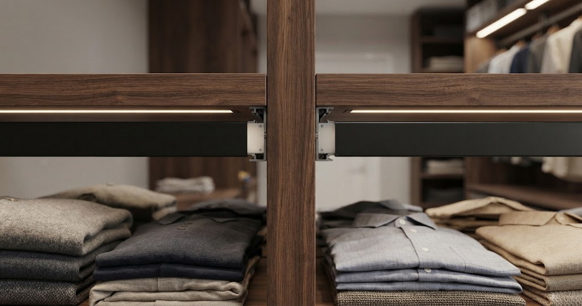
Many specifications show the strip and driver but leave the meeting point between neighboring sections to the installer. That is where an otherwise refined wardrobe can reveal abrupt diffuser stops, mismatched profile positions, or a conspicuous end cap.
Ask for a sample of the *assembled joint*, rather than approving components separately. View it both unlit and illuminated. If the design calls for lighting across cabinet bays, identify where a physical break is unavoidable and decide whether to conceal it with joinery or make it a deliberate, consistent detail.
For new custom cabinetry, back-wiring often suits repeated shelves or uprights because the maker can include cable passages in production drawings. A reachable service compartment can house an appropriate low-voltage distribution arrangement and keep the branch layout understandable for a future technician.
In a finished wardrobe, side-wiring may preserve the cabinet back. Leads can travel through planned panel openings or behind removable trim. But repeated side exits can create a crowded collection of cables unless every route is drawn—not just the route of the first light.
A hybrid may be the most practical answer. Exposed central sections might use rear entry, while a short return or removable shelf uses an end-cap exit. This is a layout choice, not permission to mix unrelated components. Confirm that the proposed fixtures, leads, connectors, driver, and controls work together.
Imagine a made-to-order wardrobe with lit shelves and a hanging area. The central bays have a removable rear service panel; an end bay sits against a finished wall. Rear entries could keep cables out of view along the central shelves. At the end bay, an end-cap lead could travel behind removable side trim.
The drawing still needs two tests. Can a technician reach and replace each section once the wardrobe is installed? And is the end-bay cable invisible from the positions where a user opens the doors? If the rear panel proves non-removable on site, or the side lead crosses a visible opening, the layout needs revision. This example is a design exercise, not a claimed Farwise installation or test result.
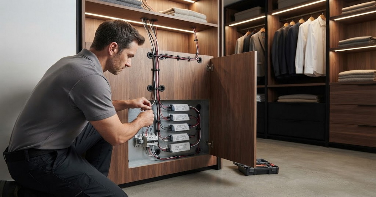
A useful approval process examines the furniture, the complete lighting system, and its future maintenance together. Component photographs cannot show whether a cable will meet a drawer runner or whether the driver will be trapped behind a fixed panel.
1. Mark the sightlines. Identify what users see with doors open and closed, including profile ends, mirrors, shelf undersides, and glossy surfaces.
2. Draw every lead exit. Show each light section, panel joint, opening, cable route, driver location, and removable cover.
3. Select the exit by location. Use rear entry where it has a protected, serviceable path; use an end-cap exit where the side route is less disruptive.
4. Review the whole circuit. Have the lighting supplier or qualified installer check the driver, controls, cable type, connections, and each fixture's permitted arrangement.
5. Build a representative sample. Illuminate a joint or multi-bay section and operate nearby doors and drawers while checking cable clearance.
6. Approve service access. Confirm that connections can be identified and that a failed section can be replaced without destroying finished joinery.
Safety suitability also needs to be established for the destination market. Do not assume that any LED strip placed inside a profile is suitable for every clothes-storage location. Verify the proposed assembly and its installation instructions, and leave building-side electrical work to a qualified professional.
A request for quotation should include the cabinet layout and intended appearance at each join, not only an image of the desired light. Ask the supplier to show the profile end treatment, lead-exit direction, protected cable path, driver and sensor locations, and the replacement method for an individual section.
Farwise Technology Co., Ltd. describes itself as a furniture-lighting manufacturer with sixteen years in the LED field and OEM/ODM support for dimensions, functions, appearance, and system layouts. Those are company-provided details, not independent evidence of performance or certification for a proposed product. Before placing a production order, request drawings, an assembled sample, installation instructions, and documentation for the *exact* configuration being supplied.
Choose back-wiring when planned cabinetry provides both a concealed rear path and real service access. Choose end-cap side-wiring when a protected side path is simpler to install, inspect, and maintain. For a project-specific assessment, send Farwise your wardrobe drawings, target installation market, preferred control method, and a sketch of the illuminated joint; request a back-entry versus end-cap-exit proposal and an assembled sample before production.
No. It can conceal the lead effectively in purpose-built furniture, but a poorly located opening or conspicuous service cover may still be visible. A well-planned side lead can disappear behind a return or removable trim.
No. A furniture-level low-voltage distribution enclosure is not automatically suitable for a hardwired mains connection. Treat the driver input and building-side wiring as a separate installation question.
Only when the specified fixtures and connection system permit it. The driver, wiring, and controls must also suit that arrangement. Individual feeds may offer a clearer layout for servicing multiple sections.
End-cap side-wiring is often less disruptive when an existing side or rear route can hide and protect the lead. Back-wiring may still work if openings can be made safely and the resulting connections remain reachable.
No. Moving the cable entry does not remove physical profile, cap, or diffuser ends. Assess those details on an illuminated assembled sample.
Place the specified driver where it can be installed according to its instructions and reached for inspection or replacement. A small hidden cavity is not necessarily a suitable service location.
Yes, provided the selected sensor, driver, and lights are compatible and their instructions allow the layout. Include the sensor and its cable path in the initial drawing rather than adding them after the cabinet is built.
1. - Lighting Line, "[Wardrobe Lights and LED Profile Integration]" — profile types, feed-through end caps, cable routing, and wardrobe lighting layouts. [lightingline]
2. - Diode LED, "[Low Voltage LED Tape Light Installation Guide]" — designated cutting points, polarity, run limits, and installation precautions. [diodeled]
3. - Diode LED, "[What Is Voltage Drop?]" — the relationship between cable runs, load, wire selection, and uneven light output. [diodeled]
4. - Diode LED, "[LO-PRO Junction Box/LED Driver Installation Guide]" — enclosure installation, wiring separation, and service access for that specific product. [diodeled]
5. - LEDVANCE, "[LED Strip System]" — planning compatible strips, drivers, profiles, accessories, and controls as a system. [ledvance]
6. - UL Solutions, "[Introduction to UL 1598, the Standard for Luminaires]" — luminaire-standard scope, including clothes-closet storage applications. [ul]


