
Views: 222 Author: Farwise Lighting Publish Time: 2026-10-24 Origin: Site


Content Menu
● Why Kitchen Hood Cabinet Lighting Needs a Different Approach
● Thermal-Conductive Aluminum PCB: How It Works
>> Why Aluminum Helps High-Heat LED Applications
>> Why the Dielectric Deserves Attention
● Double-Sided Copper FR4: What the Name Actually Means
>> How Copper Areas and Thermal Vias Improve FR4
>> When Double-Sided FR4 Makes Sense
● Aluminum PCB vs. Double-Sided FR4: Practical Comparison
● Compare the Complete Heat Path, Not Bulk Material Conductivity
>> An Aluminum PCB Is Not an Aluminum Lighting Profile
>> A Warm Profile Does Not Automatically Mean Failure
● Three Often-Missed Design Decisions for Kitchen Cabinets
>> Keep the Light Engine and Controls in Their Best Locations
>> Design for Heat Entering from the Surroundings
>> Separate Environmental Protection from Thermal Performance
● A Practical Validation Workflow Before Production
>> 1. Define the Intended Installation
>> 2. Compare Equivalent Lighting Assemblies
>> 3. Test the Finished Assembly
>> 4. Verify Temperatures Using Suitable Methods
>> 5. Review Repeatability and Serviceability
● Which PCB Should Buyers Choose?
>> Prefer Aluminum PCB When Thermal Demand Leads the Decision
>> Consider FR4 When Integration and Verified Cooling Support It
● Build a Cabinet Lighting Solution with Farwise
>> 1.Is an aluminum PCB always better for kitchen cabinet lighting?
>> 2.Can double-sided copper FR4 replace an aluminum PCB?
>> 3.Does an aluminum profile eliminate the need for PCB thermal design?
>> 4.Does solderless construction improve heat dissipation?
>> 5.Can PCB material alone guarantee a longer LED lifetime?
>> 6.What evidence should a buyer request before approval?
Choosing between a thermal-conductive aluminum PCB and double-sided copper FR4 for high-heat kitchen hood cabinets starts with one question: where will the LED's heat go? For heat-intensive lighting near a cooking area, an aluminum-based PCB is generally the stronger starting point. Double-sided FR4 remains a practical alternative when copper routing, thermal vias, mounting, and operating conditions provide an effective cooling path.
Neither material guarantees reliable lighting by itself. The board, LED package, thermal interface, aluminum profile, and surrounding environment must work together.
At Farwise Technology Co., Ltd., our focus on furniture lighting shapes the way we approach this comparison: select the system, not simply the substrate. This guide explains the trade-offs without treating material names as substitutes for application testing.

A cabinet light beside a range hood does not necessarily operate like an identical light inside a wardrobe. Its installation may encounter cooking-related heat, restricted ventilation, steam, grease, and repeated cleaning.
Location also matters. Lighting integrated into a hood appliance differs from furniture lighting mounted in neighboring cabinetry. Appliance requirements and installation instructions must take priority where applicable.
Elevated LED junction temperature can reduce light output, change color, and accelerate degradation. Junction temperature means the temperature inside the LED semiconductor—not simply the temperature of the visible board or profile.
Consequently, a successful kitchen lighting design must manage both internally generated heat and the surrounding thermal environment.
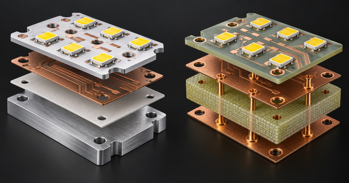
A thermal-conductive aluminum PCB is commonly an insulated metal substrate, also called a metal-core PCB.
Its typical construction includes:
- Copper circuitry supporting the LEDs and electrical connections.
- A thermally conductive, electrically insulating dielectric.
- An aluminum base that spreads heat toward the mounting structure.
The important distinction is that the aluminum base does not normally contact the live copper circuitry directly. The dielectric separates them electrically while allowing heat to pass.
An aluminum-based PCB provides an engineered path from the LED mounting area toward a broader metal surface. When properly coupled to a suitable profile or heat sink, this can reduce board-level resistance to heat flow.
That makes it attractive for compact LED modules where heat must leave a small area efficiently.
However, aluminum does not make heat disappear. A board installed with poor contact, an unsuitable interface, or an enclosed profile can still run too hot.
Two aluminum PCBs can perform differently because their dielectric systems differ.
The dielectric must balance heat transfer, electrical insulation, adhesion, and operating durability. Its contribution can become a major restriction in the board's thermal path.
For procurement, "aluminum PCB" is therefore a starting description—not sufficient evidence of thermal performance or electrical suitability.
Double-sided copper FR4 uses a fiberglass-reinforced epoxy laminate with copper circuitry on both sides.
It is not a solid copper board. Although copper conducts heat effectively, the FR4 laminate between the copper layers is comparatively resistant to through-board heat transfer.
This distinction prevents a common purchasing mistake: assuming that copper on both surfaces automatically creates a strong cooling path.
Copper areas can spread heat across the board. Thermal vias—plated connections through the laminate—can help transfer heat toward backside copper and a supporting heat sink.
Their effectiveness depends on placement, construction, and connection to the LED's thermal path.
LED package design matters, too. A via arrangement appropriate for an electrically isolated thermal pad may not be suitable for a different package. The LED manufacturer's layout guidance should govern the design.
FR4 can be attractive when the board needs flexible routing, control circuitry, or a familiar fabrication process.
It may also suit LED assemblies with manageable thermal demands and an effective mounting arrangement.
The qualification is important: acceptable performance must come from the actual layout and assembly, not from the phrase "double-sided copper."
| Decision factor | Thermal-conductive aluminum PCB | Double-sided copper FR4 |
|---|---|---|
| Primary thermal approach | Transfers heat through an insulating dielectric into a metal base | Uses copper spreading and engineered via paths |
| Through-board heat flow | Generally favorable with a suitable dielectric | More dependent on layout and via construction |
| Circuit routing | Common simple LED constructions can constrain routing choices | Often convenient for routing and control integration |
| Mounting sensitivity | Needs effective contact with the supporting structure | Needs an intentional route from copper and vias to the support |
| Electrical considerations | Metal backing requires careful insulation and assembly design | Backside copper and exposed thermal paths still require review |
| Cost assessment | Evaluate the complete assembly rather than board price alone | Added thermal features can reduce initial board-cost savings |
| Best-fit direction | Heat-intensive LED light engines with suitable metal support | Thermally manageable assemblies needing routing flexibility |
These are design tendencies, not universal rankings. A well-engineered FR4 assembly can be more appropriate than a poorly integrated aluminum-board assembly.
A frequent weakness in generic PCB comparisons is placing aluminum conductivity beside FR4 conductivity and declaring a winner.
That overlooks how the finished light actually works.
The relevant path runs from the LED junction through the package, board, thermal interface, supporting profile, and finally into the surroundings. Resistance at any stage can limit the benefit of improvements elsewhere.
The PCB carries the circuitry. The profile houses or supports the lighting assembly and may help spread and release heat.
These components serve different functions.
For a Solderless LED Aluminum Profile Light, the electrical connector arrangement must also remain distinct from the thermal mounting arrangement. Eliminating an installation solder joint does not prove effective heat transfer between the PCB and profile.
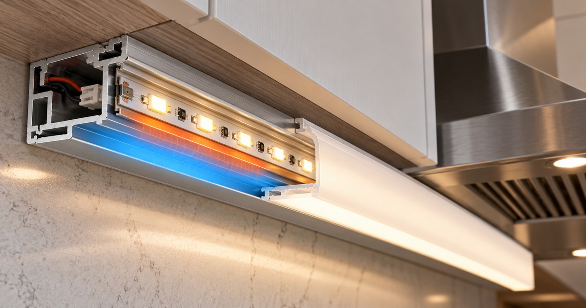
A profile warming during operation can indicate that heat is reaching it as intended. Conversely, a relatively cool profile may coexist with a hot LED if thermal contact is poor.
Touch alone cannot establish junction temperature or compliance.
The useful question is whether measured component and assembly temperatures remain appropriate under the intended operating conditions.
The LED board and control electronics do not always need to share one substrate or one thermal environment.
A possible architecture uses an aluminum PCB for the LED light engine and a separate FR4 board for control functions.
This can simplify competing thermal and routing requirements. It also introduces wiring, connection, packaging, and service considerations, so it should be evaluated rather than assumed superior.
A metal mounting surface is not always a useful cooling destination.
If a nearby hood structure or cabinet mounting area becomes hotter than the lighting assembly, contact can transfer heat toward the light rather than away from it.
The design review should therefore establish where heat originates, which surfaces become hot, and whether the intended mounting structure remains an effective thermal outlet.
Neither aluminum backing nor FR4 construction makes a finished light automatically resistant to moisture, grease, or cleaning products.
Protective housings, seals, coatings, connectors, and compatible materials require separate assessment.
Protection can also affect cooling and service access. The enclosure and thermal design should therefore be developed together, rather than adding protection after the light engine has been finalized.
The following workflow is a proposed engineering approach, not a report of completed Farwise testing.
Document whether the light sits inside a hood, below adjacent cabinetry, or within a decorative enclosure.
Identify the mounting surface, ventilation, expected cooking exposure, cleaning method, and service access.
Where practical, compare the aluminum PCB and FR4 options using equivalent LEDs, drive conditions, optics, and installation arrangements.
Otherwise, a difference attributed to the substrate may actually come from a different LED package, mounting method, or electrical operating point.
Evaluate the light with its actual profile, diffuser, interface material, connectors, and mounting hardware.
A bare-board demonstration cannot establish the performance of a recessed cabinet installation.
Include representative cooking-related conditions and permitted operating modes rather than relying only on an open-bench test.
Use the LED manufacturer's recommended measurement location and method to assess junction temperature.
Infrared imaging can help locate hot areas, but reflective metal surfaces require careful interpretation. A surface image alone does not establish the temperature inside the LED.
Confirm that assembly variation does not undermine thermal contact.
Review board seating, interface application, connector engagement, fastening, and replacement access. A successful prototype is not enough if routine production cannot reproduce its mounting quality.
Start with an aluminum-based PCB when the LED light engine faces concentrated heat generation and has access to an appropriate heat-spreading structure.
It is particularly worth evaluating when compact packaging leaves limited freedom to create extensive FR4 thermal paths.
Still, ask for assembly-level validation. The material label does not establish the finished product's temperature margin.
Consider double-sided copper FR4 when routing flexibility or integrated electronics provides a meaningful advantage.
Require evidence that the copper layout, thermal vias, LED package, and mounting arrangement work together under the intended conditions.
Do not approve FR4 solely because its board quotation is lower. Additional fabrication features, assembly controls, or cooling hardware can change the overall economics.
Farwise Technology Co., Ltd. brings 16 years of LED lighting manufacturing experience to furniture and interior lighting projects. Our product scope includes Solderless LED Aluminum Profile Light solutions and lighting for cabinets, wardrobes, bathroom furniture, and beds.
We support OEM/ODM customization across dimensions, functions, appearance, and lighting concepts.
For a kitchen hood cabinet project, send Farwise your installation drawing, mounting details, intended operating environment, control requirements, and service expectations. Request a project-specific review of the PCB, profile, connection method, and validation plan before finalizing production.
The objective is a lighting solution matched to its real installation—not a material upgrade without a clear thermal purpose.
No. It generally offers a favorable board-level thermal path, but its value depends on the dielectric, mounting interface, profile, and surrounding conditions. FR4 can remain suitable when the complete assembly demonstrates adequate performance.
Sometimes. Replacement requires thermal and electrical review, not just matching the board outline. The FR4 design may need suitable copper areas, thermal vias, and a revised mounting interface.
No. Heat must reach the profile effectively. Poor board-to-profile contact can restrict cooling even when the profile itself is well designed.
Not inherently. Solderless describes an electrical connection approach. Thermal performance depends on the LED package, PCB construction, interface, mechanical contact, and heat-releasing surfaces.
No. Junction temperature affects LED degradation, but lifetime also depends on operating conditions and other components. A substrate choice alone cannot support a finished-product lifetime claim.
Request a defined board construction, an explanation of the thermal path, representative assembly-temperature verification, and the relevant electrical and environmental assessment. Evidence should describe the intended installation, not only a bare-board sample.
1. - [Cree LED — *Optimizing PCB Thermal Performance for XLamp® LEDs*, application note CLD-AP37, Revision 4A.] Technical basis for FR4 construction, thermal vias, metal-core boards, manufacturing trade-offs, and real-condition temperature verification. Its guidance applies to the specified LED packages and should not be generalized without review. [downloads.cree-led]
2. - [Cree LED — *Thermal Management of XLamp® LEDs*, application note CLD-AP5, Revision 5.] Technical basis for junction-temperature effects, the complete thermal path, interface materials, heat sinks, and measurement considerations. [assets.cree-led]
3. - [TCLAD Inc. — *Insulated Metal Substrate IMS®*.] Manufacturer explanation of copper circuitry, thermally conductive insulating dielectrics, and metal-base construction. Manufacturer-specific claims are not presented here as guarantees for all aluminum PCBs. [tclad]
4. - [Henkel/Bergquist — *Thermal Management for LED Applications*.] Supporting explanation of insulated metal substrates and dielectric functions in LED thermal management. [dm.henkel-dam]


